Notes on Temperature Sensors

Notes on Temperature measurement and sensors.

1. As of May 20,2019, the International System of Units (SI) was redefined and adopted.
In this adoption, all base units of measure (length, time, mass, electrical current, thermodynamic temperature, amount of substance, luminous intensity) have been defined by the seven natural constants (speed of light, Planck constant, elementary charge, Boltzmann constant, Avogadro constant, luminous efficacy constant and hyperfine transition frequency of Cesium). The International Temperature Scale (ITS-90) reflects the thermodynamic temperature scale, expressed in degrees Kelvin, by a series of reference points. Each point is a physical state of a material, such as hydrogen triple point (0K or -259.34C) and the freezing point of platinum (2042.15K or 1769.00C) .

2. In US, the organization responsible for all thermometry standards, research and calibration is NIST (National Institute of Standards & Technology). Its Thermodynamic metrology group maintains and develops national standards of temperature and supports of all types of contact thermometers calibration methods. https://www.nist.gov/pml/weights-and-measures/metric-si/si-units

3. There are two classes of temperature sensors: absolute and relative class. The absolute temperature sensors have a reference calibration point such as absolute zero on the thermodynamic scale, or any other reference point such as “ice water triple point”. Some examples of absolute sensors are RTDs and thermistors. An example of the relative sensor class are thermocouples. The thermocouple has to have a “reference junction” placed at a known temperature to measure the difference between the junction and the point of measurement. https://gerelectronics.com/usb-temperature-sensor/

4. A very large majority of all temperature sensors used in commerce and industry are thermocouples, RTD and thermistors.

5. All temperature sensors utilize a natural phenomenon that were discovered in the last few centuries and then studied and quantified scientifically. For example, in 1821, Thomas Johann Seebeck, accidentally observed that by joining wires of different metals end to end, there was a magnetic disturbance detected by his compass. This knowledge stayed unexplored until 1826 when A.C. Becquerel suggested that Seebeck’s effect could be used to measure temperature. It took another 60 years for the first thermocouple temperature sensor to be constructed by Henry LeChatelier.

6. Today the thermocouple temperature sensors are characterized by American Standards ANSI MC 96.1. https://blog.ansi.org/2018/10/thermocouples-calibration-table-ansi-mc961/

7. At about the same time, in 1887, Hugh Callendar published a paper describing how to use platinum as a temperature sensor. This platinum sensor was markedly different from the thermocouple as it utilized a physical property of platinum and other metals called thermo-resistivity. The thermo-resistive effect was first noted by Sir Humpry Davy in 1821. The RTD, as it is called nowadays, is an absolute sensor. https://gerelectronics.com/usb-temperature-sensor/

8. Thermistors have come to use in more recent times. It name is an abbreviation of “thermal resistor”. They are based on the same thermo-resistance effects discovered in the 1800’. However, they are not made of pure metals, but of metal oxides. Its temperature response (or transfer function) depends on its physical dimensions and the intrinsic resistivity of the metal oxide. After many years of experimental measurements, the relationship between the resistance and absolute temperature for a thermistor has been agreed to be a non-linear equation of the logarithm of thermistors resistance, R, and a polynomial equation of third order in temperature, T. For practical temperature measurements, because the equation is non-linear, the selection of the measurement range becomes of paramount importance. https://gerelectronics.com/usb-temperature-sensor/

9. In the following posts we will describe each of these devices in more details.


New wireless microHUB from Yoctopuce SARL.

COMING SOON!

Connect multiple sensors to a LTE cellular network!

The new long-range YoctoHub based on the LTE technology. It supports the LTE-M (LTE Cat. M1) and NB-IoT (LTE Cat. NB1) standards. We selected these technologies because they are the easiest to implement for small and medium-sized businesses. Indeed, the YoctoHub doesn’t require setting up any particular infrastructure, nor any complex contract with telecom providers: a simple SIM card covering these technologies is enough.

Worldwide coverage for these networks is good, and the module allows you to accommodate frequency bands used in the different regions of the world. Unlike the LoRa and Sigfox networks using unlicensed frequency bands, the LTE technologies have a certain guarantee of stability thanks to the fact that the bandwidth use is controlled by the providers. The benefit is reduced risk of a decrease in the signal/noise ratio as and when other long-range networks deploy on the same frequency domain.

Hub 4G/LTE
The new YoctoHub-GSM-4G

The YoctoHub-GSM-4G will replace the YoctoHub-GSM-3G-EU and of the YoctoHub-GSM-3G-NA.  at a lower price point.

Moreover, it consumes somewhat less current, and when the coverage is good, it connects faster. In countries where LTE-M coverage is not available, the NB-IoT bandwidth is lower than that of 3G. For simple HTTP callbacks, it normally is not an issue.

For less technologically advanced countries which have neither LTE-M nor NB-IoT, the module can connect to a 2G network (GPRS or EDGE) on the four most widely used frequency bands.

For full specifications please visit https://gerelectronics.com/product/yoctohub-gsm-4g-lte/.


Beta Test Offer!

For several years, we have been offering different YoctoHubs to connect Yoctopuce USB sensors directly to a network, without using a computer. But as you may have noticed, we didn’t throw ourselves headlong into cutting-edge technologies, especially when standards are split: LoRa, Sigfox, LTE-M, NB-IoT, 5G… With the multiplication of networks aimed at the IoT, we had to wait for the landscape to become clearer, because we couldn’t do it all and we had to choose the solution which would best suit our customers. But here it is, we finally made our choice, and it’s almost ready.

The new long-range YoctoHub is based on the LTE technology, on which the 4G and 5G networks are based. It supports the LTE-M (LTE Cat. M1) and NB-IoT (LTE Cat. NB1) standards. We selected these technologies because they are the easiest to implement for small and medium-sized businesses. Indeed, the YoctoHub doesn’t require setting up any particular infrastructure, nor any complex contract with telecom providers: a simple SIM card covering these technologies is enough, as previously with 2G and 3G technologies.

The worldwide coverage for these networks is good, and the module allows you to accommodate frequency bands used in the different regions of the world. Unlike the LoRa and Sigfox networks using unlicensed frequency bands, the LTE technologies have a certain guarantee of stability thanks to the fact that the bandwidth use is controlled by the providers. The benefit is reduced risk of a lowering of the signal/noise ratio as and when other long-range networks deploy on the same frequency domain.

The new YoctoHub-GSM-4G

Apart from the technology which changes, the functions of the YoctoHub-GSM-4G are essentially the same as that of the YoctoHub-GSM-3G-EU and of the YoctoHub-GSM-3G-NA. These two products are going to be replaced by the new one, which we can even sell at a lower price point than its predecessors. Moreover, it consumes somewhat less current, and when the coverage is good, it connects faster. The only disadvantage, if you are in a country where LTE-M coverage is not available, is that the NB-IoT bandwidth is lower than that of 3G. But for simple HTTP callbacks, it normally is not an issue. For less technologically advanced countries which have neither LTE-M nor NB-IoT, the module can connect to a 2G network (GPRS or EDGE) on the four most widely used frequency bands around the world.

At this point in time, we are looking for some Beta-testers in different countries to make sure that it works globally. If you think that you’ll need this module in the future, here is our offer:
• We sell you a new functional module for only $40, which is an 80% discount.
• You start testing the module in the next 1-2 weeks, to either confirm that it works well or to signal potential problems so that we can correct them with an update.
• If a hardware modification are required to solve an issue, you’ll receive a corrected version free of charge. Thus, at the end of the test period, you’ll have a fully functional hardware.
Interesting, isn’t it? So, contact us at info@greenenergyresearch.com to register for the Beta-test, telling us the region intended for the deployment, the type of network that you think you are going to use (NB-IoT or LTE-M), and if you already know which phone provider you are going to work with.

The offer is limited to one or two Beta-tests by network type and by country. This offer is on a first come, first serve basis!

All decisions are made by Yoctopuce SARL and are final.

Phidgets Hex Walker First Steps

This Hex Walker project demonstrates the use of the RCC1000 servo controller with a large number of servos in a coordinated fashion. What better way to do that than with a walking robot?

Hardware

The hex walker is derived from the Lynxmotion AH2 walking robot. It features 6 legs using 12 servos for basic movement. These servos are plugged into the RCC1000 – 16x RC Servo Phidget, which in turn is plugged into a VINT Hub. For this project, the walker will be tethered to power and a long VINT cable for simplicity.

Software

Libraries And Drivers

This project assumes that you are somewhat familiar with the basic operation of Phidgets (i.e. attaching and opening devices, reading data, etc) and with running examples in the Phidget Control Panel .

Controlling The Hex Walker

The first step is to connect to the the twelve servo channels required to make the robot walk. For simplicity, the servos were connected in a specific patern to allow easy selection.

The next step of programming the robot to walk is to verify all servos move the right way. For this robot, it was found that the servos on the opposite sides of the robot were reversed. This is compensated for by reversing the signal to the servos on one side of the bot.

To assist with this, a leg-moving funciton was implemented as follows:


void setLegPos(PhidgetRCServoHandle* servos, int index, double pos) {
    legsDone[index] = 0;

    if (isHorizontal(index)) {
        if (!isLeftSide(index))
            pos *= -1;
        PhidgetRCServo_setTargetPosition_async(servos[index], 90 + pos, NULL, NULL);
    } else {
        if (isLeftSide(index))
            pos = 180 - pos;
        PhidgetRCServo_setTargetPosition_async(servos[index], pos, NULL, NULL);
    }
}

Note the use of the asynchronous calls to set servo positions (PhidgetRCServo_setTargetPosition_async) in order to better coordinate their movement.

For movement, the legs are grouped in tripods consisting of the front and back legs of one side and the middle leg of the other. This ensures the robot remains stable at all times while it walks. In order to walk, the robot lifts one tripod and moves it forwards while simultaneously moving the legs on the ground towards the rear. Then, it repeats the same cycle for the next set of legs. This motion propels the robot forwards.

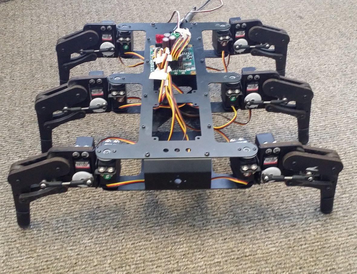
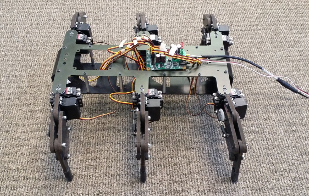
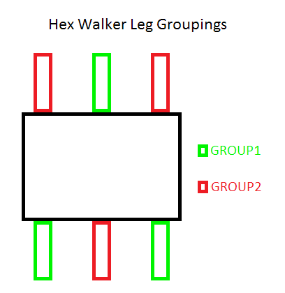
In order to turn, one tripod is lifted while the other set rotates in the given direction. To turn left, the right legs are moved forwards while the left legs are moved back, and vice-versa.

For control from the joystick, these movements are combined to allow for more freedom of motion.

The code snippet below shows how the walking algorithm is implemented for this demonstraiton. In this case, the joystick value is sampled and traslated into the relative size and direction of the step (velocity), with the turning amout (turnOffset) added to allow turning while on the move. In addition, if the joystick position is close to centre, the robot will enter a NEUTRAL state, where the legs won’t move until there is more input.


void walk(PhidgetRCServoHandle* servos, PhidgetVoltageRatioInputHandle* axes) {
	double turnOffset;
	double velocity;
	double yAxis;
	double xAxis;

	PhidgetVoltageRatioInput_getVoltageRatio(axes[0], &xAxis);
	PhidgetVoltageRatioInput_getVoltageRatio(axes[1], &yAxis);

	turnOffset = xAxis;
	velocity = yAxis;

	if (!checkLegsDone())
		return;

	//If the joystick is centred, force input to zero 
	if (fabs(xAxis) < 0.1 && fabs(yAxis) < 0.1) {
		velocity = 0;
		turnOffset = 0;
		//Set stepTracker to NEUTRAL after movement to allow legs to centre themselves first
	}

	//If stopped and there is new input, start with GROUP1
	if (stepTracker == NEUTRAL && velocity != 0 && turnOffset != 0)
		stepTracker = GROUP1;

	//Perform the step
	if (stepTracker == GROUP1 || stepTracker == GROUP2)
	{
		if (stepTracker == GROUP2)
			turnOffset *= -1;
		
		//Start lifting legs
		setLegPos(servos, tripod[stepTracker][V][F], VMAX/4);
		setLegPos(servos, tripod[stepTracker][V][M], VMAX/4);
		setLegPos(servos, tripod[stepTracker][V][R], VMAX/4);
		
		waitLegsDone();
		//Move all legs to next positions, finish raising legs
		setLegPos(servos, tripod[stepTracker][V][F], VMAX);
		setLegPos(servos, tripod[stepTracker][V][M], VMAX);
		setLegPos(servos, tripod[stepTracker][V][R], VMAX);

		//Move raised legs to their next positions
		setLegPos(servos, tripod[stepTracker][H][F], HMAX * (velocity + turnOffset));
		setLegPos(servos, tripod[stepTracker][H][M], HMAX * (velocity - turnOffset));
		setLegPos(servos, tripod[stepTracker][H][R], HMAX * (velocity + turnOffset));

		//Move grounded legs to move the robot
		setLegPos(servos, tripod[!stepTracker][H][F], HMAX * ((-velocity) + turnOffset));
		setLegPos(servos, tripod[!stepTracker][H][M], HMAX * ((-velocity) - turnOffset));
		setLegPos(servos, tripod[!stepTracker][H][R], HMAX * ((-velocity) + turnOffset));

		waitLegsDone();

		//Put raised legs down
		setLegPos(servos, tripod[stepTracker][V][F], 0);
		setLegPos(servos, tripod[stepTracker][V][M], 0);
		setLegPos(servos, tripod[stepTracker][V][R], 0);
		//Decide to take another step or wait for further input
		if (velocity == 0 && turnOffset == 0)
			stepTracker = NEUTRAL;
		else
			stepTracker = ((stepTracker == GROUP1) ? GROUP2 : GROUP1);
	}
}

In addition to walking, when the joystick button is pressed the walker crouches and tilts in the direction of the joystick. Once the button is released, the walker stands up and continues walking. This is accomplished by bending the legs on one side of the bot while extending those on the other, as follows:


void lean(PhidgetRCServoHandle* servos, PhidgetVoltageRatioInputHandle* axes) {
	double yAxis;
	double xAxis;

	PhidgetVoltageRatioInput_getVoltageRatio(axes[0], &xAxis);
	PhidgetVoltageRatioInput_getVoltageRatio(axes[1], &yAxis);

	if (!crouched) {
		//set vertival servos to high speed for better tracking of the joystick
		for (int i = 0; i < NUM_SERVOS; i++) {
			if(!isHorizontal(i)) 
				PhidgetRCServo_setVelocityLimit(servos[i], 9000);
		}
	}

	setLegPos(servos, LFV, (VMAX / 2) + (xAxis * -(VMAX / 4)) + (yAxis * (VMAX / 4)));
	setLegPos(servos, RFV, (VMAX / 2) + (xAxis *  (VMAX / 4)) + (yAxis * (VMAX / 4)));

	setLegPos(servos, LMV, (VMAX / 2) + (xAxis * -(VMAX / 4)));
	setLegPos(servos, RMV, (VMAX / 2) + (xAxis *  (VMAX / 4)));

	setLegPos(servos, LRV, (VMAX / 2) + (xAxis * -(VMAX / 4)) + (yAxis * -(VMAX / 4)));
	setLegPos(servos, RRV, (VMAX / 2) + (xAxis *  (VMAX / 4)) + (yAxis * -(VMAX / 4)));
	crouched = 1;
}

void standUp(PhidgetRCServoHandle* servos) {

	if (crouched) {
		for (int i = 0; i < NUM_SERVOS; i++) {
			if (!isHorizontal(i))
				PhidgetRCServo_setVelocityLimit(servos[i], 360);
		}

		setLegPos(servos, LFV, 0);
		setLegPos(servos, RFV, 0);

		setLegPos(servos, LMV, 0);
		setLegPos(servos, RMV, 0);

		setLegPos(servos, LRV, 0);
		setLegPos(servos, RRV, 0);

		crouched = 0;
	}
}

The program is controlled by a simple loop that determines the next action based on the state of the joystick button.


while (!kbhit()) {
    PhidgetDigitalInput_getState(button, &buttonState);
    if (!buttonState) {
        if (crouched)
            standUp(servos);
        walk(servos, axes);
    } else
        lean(servos, axes);

    ssleep(0.02);
}

For a leg up on similar projects, you can download the source code for this project: Download Source Code

Electric home brewery with Phidgets

Interested in building an all electric home brewery without having to rely on propane? Check out the series that does just that. Part 1 covers the brew kettle, and part 2 will cover the fermentation chamber.

“I live in Calgary, where we have snow and subzero temperatures for a large chunk of the year. I wanted to be able to brew year-round, so that meant brewing inside. Propane inside is a really bad idea, so that meant going all-electric. Phidgets has almost everything you need to build a control box for an electric brew kettle.

There is some good information online about building an electric kettle, but a lot of it glosses over the control portion, focussing instead on kettle conversion. Even when control is discussed, it’s generally done with industrial PID controllers. I wanted to write my own software to control the process. This article focuses on the control panel, which is built around a PhidgetSBC4, with software written in C.

I run an EBIAB (electric brew-in-a-bag) setup, so I’m only controlling / monitoring a single kettle, but it would be easy to scale up to multiple inputs/outputs.”

See the full article at https://www.phidgets.com/?view=articles&article=Brewing1 for instructions, hardware, source code and the works.

Verified by MonsterInsights